Motorcycle exhaust · Flow simulation
Motorcycle Muffler CFD
This study evaluated a patented venturi concept within a motorcycle muffler. SolidWorks flow analysis investigated how geometry and inlet flow affected pressure, velocity, and local flow patterns around the venturi and at the outlet.
- My contribution
- CFD investigation of the muffler assembly and flow comparisons.
- Study question
- How does the venturi geometry affect flow relative to the baseline configuration?
- Outcome
- Simulation comparisons of both configurations at the shared 300 CFM inlet condition.
01 / Assembly
Understanding the assembly
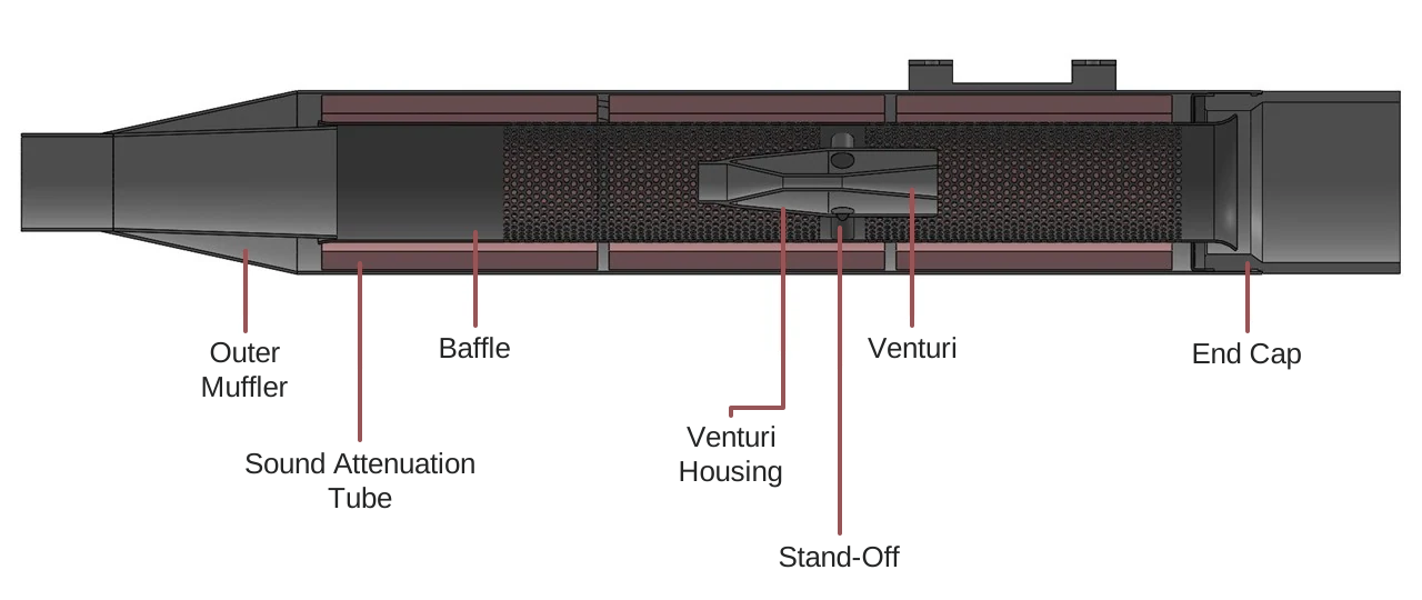
The muffler was studied as a system of interacting components. The labeled cutaway connects the outer muffler, sound attenuation tube, baffle, venturi housing, stand-off, venturi, and end cap to the component photographs.
Sound attenuation tube
Outer muffler & end cap
Venturi & baffle assembly
02 / Study questions
Asking specific geometry questions
The study investigated three geometry questions to understand their effects on pressure, velocity, and local flow behavior.
- How do the size and number of holes around the venturi throat affect the flow?
- How does the length of the diverging section affect flow through the holes and around the venturi housing?
- How does the length of the non-perforated baffle section affect pressure and velocity between the venturi and the baffle?
03 / Development
Comparing the flow fields
The simulations used air, with refined mesh around and inside the venturi. Inlet flow rates ranged from 100–600 CFM, with an outlet pressure of 101.325 kPa.
The publicly shared comparison presents the 300 CFM condition with and without the venturi. It focuses on velocity at regions of interest while retaining the original scale and units. These are simulation outputs for the muffler study.