Zander Slavitz
Automating an RC car
Professor Craig Beal, Bucknell University
Introduction
Background
-
In the United States there’s an estimated 6.8 million crashes a year, 90% of those caused by driver error1,2
Product Goals
-
Final goal was a visual aid for driver that incorporates weather conditions, speed, and direction of car to reduce accidents by loss of handling
-
A scaled-down driving simulation with a remote control (RC) car was needed
Methods
-
Standard web camera was fixed to ceiling above a platform colored white to simplify color filtering
-
RC controller connected to Arduino to program RC car speed and turning angle
-
RGB image filtering and a circle identification algorithm on web camera image, red and blue stickers placed on RC car were continuously tracked a maximum 30 times a second

RC controller connected to Arduino

Red and blue stickers to simplify image filter

Testing platform
Results
Proof of Concept

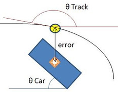
Distance and angle offset from circular track determined steering angle
𝛿 = Steering change
Ke = Error constant
Ka = Angle constant
Calculates difference between angle of car and angle of track

Program physically validated
Expanding Virtual Track Design
Adjusted tracking mechanism to calculate angle tangent to each point on the track to compute difference between car angle and track

Autonomous tracking with tangent angle calculation test
Feed-Forward Algorithm, Low Velocity


Steering angle of each turn was calculated as a feed-forward input, then the feedback algorithm corrected car orientation and distance to that point on the track

Low velocity validation of feed-forward steering algorithm
Feed-Forward Algorithm, High Velocity


An additional feedback algorithm was investigated: projection distance 'dla' from centroid on red sticker

Trial of autonomous driving with feedback mechanism that takes position offset at a distance 'dla' in front of red sticker centroid, average speed of 1.15 m/s
Future Research
The webcam shoots at rate at 30 frames/second, and with the RC car at 1.1 m/s, each frame captures the RC car in intervals of 1.5" apart. The software updates with every frame, thus restricting car speed to provide enough information to maintain the car on its course. If an algorithm extrapolated car position before the next frame, enabling better adhesion to track at a higher speed, likely close to or above 2 m/s.
References
1) NHTSA. "Agressive Driving." Home | National Highway Traffic Safety Administration (NHTSA). N.p., n.d. Web. 4 Feb. 2013. <http://www.nhtsa.gov/people/injury/aggressive/aggproplanner/page05.htm>
2) NHTSA. "U.S. Department of Transportation." National Motor Vehicle Crash Causation Survey. N.p., n.d. Web. 4 Feb. 2013. <www-nrd.nhtsa.dot.gov/Pubs/811059.PDF>.